Jiangsu Runfeng Jiu Seals Co., Ltd.
Guangzhou JRS Machinery Equipment Co.,Ltd since its inception in 2004, has been
engaged in hydraulic seals business of excavators, loaders,
bulldozers,breaking hammers and other seals have in-depth study.
Through more than 15 years of efforts, JRS has accumulated a large
number of domestic, imported excavators and broken hammer seal
data, and for new products and new models of seals data constantly
updated, finishing and perfect. After more than 10 years of
practical inspection, product quality is stable and reliable, has
accumulated rich experience and good reputation, with long-term
cooperation at home and abroad friends and customers, "take care of
the equipment,improve the efficiency and honesty" concept won the
customers at home and abroad highly recognized and widely praised
In the future, we will continue to maintain a rigorous scientific
attitude, to maintain a professional, precise style of work, and
strive to become the best supplier of Chinese seal repair kits,
look forward to your cooperation!
Service
Main business:
1. Excavator series: large, medium and small cylinder repair kits,
hydraulic pump repair kits, distribution valve repair kits, gear
pump oil seals, riser oil seals, skeleton oil seals, oil separation
repair kits, walking pump repair kits, rotary pumps Repair kits, tightening cylinder repair kits, walking mirrors,
hydraulic pumps and engine couplings, operating rod oil seals,
crankshaft front and rear oil seals, pilot pump repair kits, repair
kits for various models, and various seal parts;
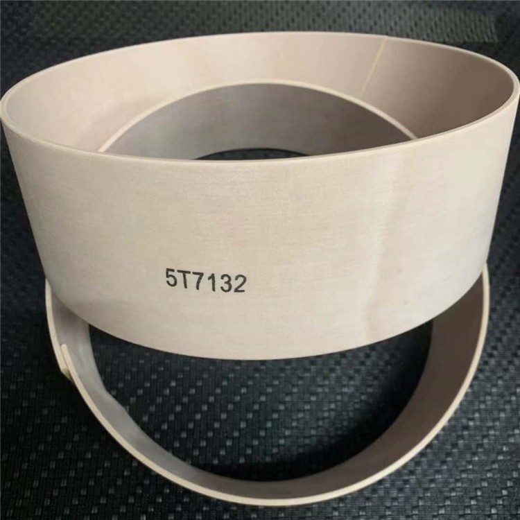
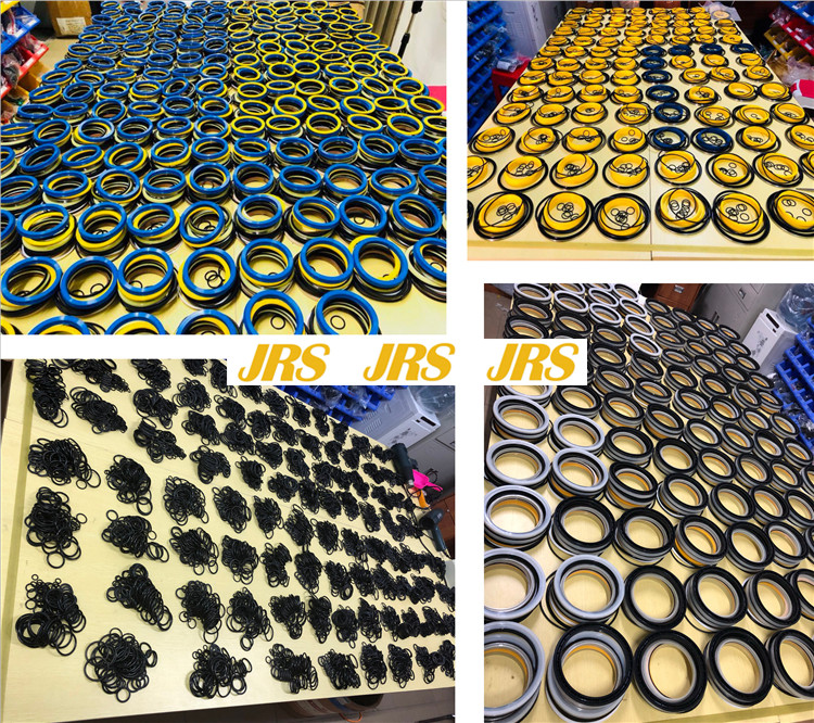
2. O-rings, Y-rings, U-rings, star-shaped rings, lace-shaped rings,
drum-shaped rings, dust-proof rings, combined rings, Glyy rings,
ster rings, gaskets, guide belts, mechanical water seals Other seals;
3. Hydraulic seals for all excavators such as Komatsu, Hitachi,
Carter, Hyundai, Sumitomo, Kobelco, Kato, Doosan Daewoo, EC, etc.;
4. Hydraulic seals for loaders, bulldozers, and breakers;
5. Pusher, floating oil seal/mirror, connecting glue, leather cup,
etc.